How to draw the berth
The orientation of the water to the land in your yard model determines how you draw your berths. When you draw your berths in Yard Editor, N4 records the latitudinal and longitudinal coordinates of the Anchor point that you chose. You must enter the Facing Direction--which is the angle, clockwise from true North--of the direction of the water with respect to the real-world water front line.
Although your berth will appear as a rectangle in the Yard Editor yard map, N4 uses only the information from the two long sides of the rectangles (that is, the long side dimension along the water front line).The length (long side dimension) of the rectangle is visually important in the yard map, and it also determines the length of the berth.
The width (short side dimension) of the rectangle is not important. How wide or narrow you draw the rectangle is based only on how wide you need it to be to see it in the yard map. For example, you can draw it to be wide enough to display the Name. If your quay has quay crane lanes or other elements in the yard that are modeled as blocks in Yard Editor, you may want to draw the berth so that the width of the berth rectangle does not overlap those elements.
Follow these guidelines as you draw your berth:
-
Use a CAD overlay on your yard map image to help you place elements on the map. N4 does not support fine-tuning the Anchor Latitude and Anchor Longitude fields, so if you make a mistake with those fields, you must delete and then redraw the berth.
-
You must draw a straight line parallel to the water's edge. In addition,  (the Berth tool) does not support curved lines.
-
The Facing Direction must be at an exactly 90 degree angle from the real-world water front line. You must determine the angle of the Facing Direction with respect to compass true North in a clockwise direction and enter it into the Berth form. You can fine-tune the value after you create the berth. The accuracy of this field impacts the offset calculations of berths, bollards, and vertices.
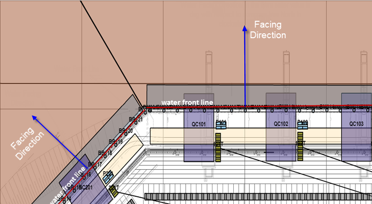
Example 1: Facing Direction at a 90 degree angle
Example 2: Facing direction at a 90 degree angle
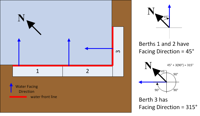
In the image below, the quay has two berths, each with a different water Facing Direction. The water Facing Direction is at a 90 degree angle to the water front line -- a conceptual line shown below in red.
This long side dimension underlays or overlaps other important elements such as Quay Crane transfer zones or lanes, so that it reflects the physical layout of the quay. Use the CAD markings or yard map grid to draw it to a precise length. The Length field in the Berth Model form (on page 1) does not reflect the drawn length of the berth rectangle until you apply the yard model changes to the Yard.
-
Use  (the Yard Path tool) to draw a line that measures the length of the berth that you drew.
-
Click the corner at one end of the long side.
-
Double-click at the far end of the berth.
The Yard Path form opens and the value in the Distance field is the length of the rectangle.
-
Cancel out of the Yard Path form.
Example 3: Draw a berth that is parallel to the X axis
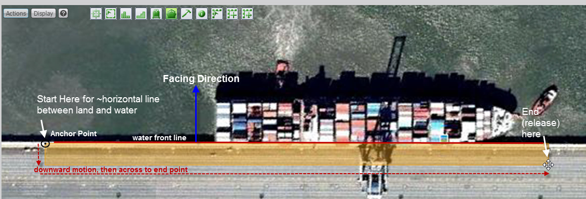
-
From the top right corner to the left top corner
-
From the left top corner to the bottom.
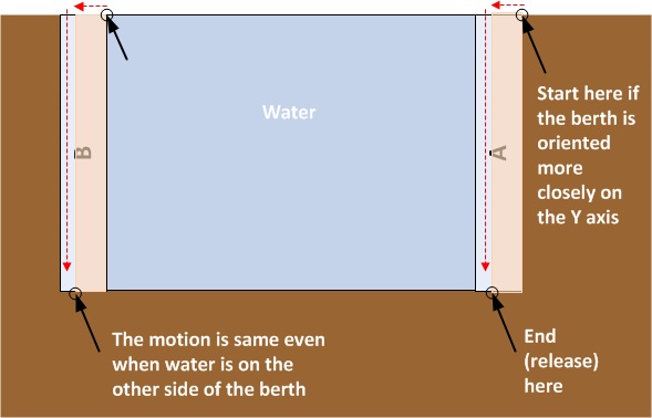
Example 4: Draw a berth that is parallel to the Y axis